
PoolBox V4
What is PoolBox
PoolBox can measure pH, ORP and water temperature, and control equipment associated with the pool. Its relays are not simple switches: once a function is assigned in Ysland, the device applies the internal logic for filtration, pH dosing, disinfection or other configured functions.
What this manual covers
This document covers the physical installation. Functions, setpoints, algorithms, schedules and calibrations are configured later in the Ysland platform.
Contents
Before you begin
Check the supplied items
- PoolBox V4 and serial number.
- pH and ORP probes, if included in the kit.
- 3-wire temperature probe.
- Saddles, probe holders and thermowell, according to the supplied kit.
- Required mounting hardware and cable glands.
Decide what you will control
Before wiring, identify the equipment to be connected to PoolBox: filtration, salt chlorinator, peristaltic pumps, lighting or other auxiliary equipment.
What you will need
Terminals, cover and fasteners.
Adjustable or socket wrench.
Saddles and probe holders.
Confirm absence of voltage and carry out checks.
Prepare the conductors.
Neat cable termination.
Temperature thermowell, where applicable.
Cable, protective devices and contactor, if required.
Isolate the power and work safely
Installation must be carried out by qualified personnel. Before opening the panel or connecting any conductor, disconnect the power supply and verify that no voltage is present.
Sequence
- Identify the circuit that will supply PoolBox.
- Switch off the relevant circuit breaker, residual-current device or isolator.
- Label or lock out the switchgear where appropriate.
- Use a suitable instrument to verify that no voltage is present.
- Do not restore power until step 12.
Protective devices
- 30 mA residual-current device.
- Circuit-breaker protection suitable for the incoming supply.
- Do not work on PoolBox while it is energized.
- Do not install where the unit will be directly exposed to rain, intense sunlight or condensation.
Location, mounting and cable entry
Location
Mount PoolBox on a vertical wall or stable surface, with enough access for maintenance.
Protection
Avoid direct sunlight, rain, excessive humidity, condensation and heat sources.
Cable entry
Plan the power, probe and control wiring before feeding the conductors through the lower cable glands.
Identify the PoolBox V4 board
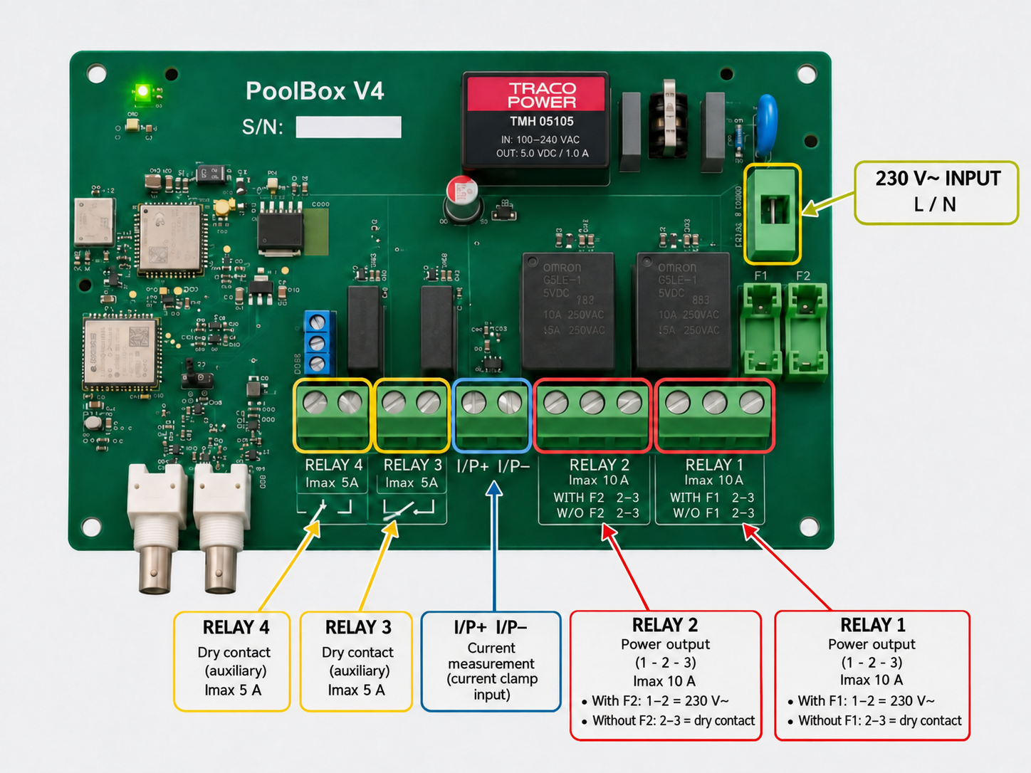
L / N
Auxiliary dry contact · Imax 5 A
Current measurement (current clamp)
Power output · Imax 10 A · with F1/F2 = 230 V~, without = dry contact
PoolBox power supply
Power supply data
| Voltage | 230 V AC ±10 % |
| Frequency | 50/60 Hz |
| Residual-current device | 30 mA |
| Protective earth | Required |
Procedure
- Feed the cable through the designated mains entry.
- Connect live and neutral to the marked terminals.
- Connect the protective earth according to the unit configuration.
- Check that the terminals are tight and no bare copper is exposed.
Probe installation
pH and ORP
- Install saddles/probe holders on the return pipe.
- Drill with a 12 mm bit where required for the installation.
- Avoid impacts to the glass body.
- Install vertically or at a slight angle, with the tip pointing down.
- Avoid air bubbles and high turbulence.
- Connect the pH and ORP probes to their respective BNC connectors.
Temperature · 3 wires
| Color | Terminal | Function |
|---|---|---|
| Red | VCC | Supply |
| Yellow | INPUT | Signal |
| Black | GND | Ground |
Relays and electrical wiring
Switched 230 V~ output
Install F1 for R1 or F2 for R2 and use terminals 1–2.
Typical use: a compatible 230 V~ load, such as a peristaltic pump or salt chlorinator.
Dry contact
Physically remove F1/F2 and use terminals 2–3.
Typical use: a run input, contactor coil or self-powered unit.
R1 / R2
20 A máx. · 250 V AC.
| Mode | Fuse | Terminals |
|---|---|---|
| 230 V~ output | Installed | 1–2 |
| Dry contact | Removed | 2–3 |
R3 / R4
5 A máx. · 230 V AC.
Auxiliary relays for additional functions. The specific function is assigned in Ysland.
Current measurement · I/P+ / I/P−
What it provides
It can show whether the pump is actually running, record effective filtration time and support functions such as dirty-filter detection.
Operating limit
This guide uses a recommended operating limit of 25 A.
Two distinct concepts: control and measurement
Practical V4 wiring diagrams
230 V peristaltic pump supplied directly from R1/R2
terminals 1–2
Filtration pump · dry contact + independent measurement
dry contact
Pump supplied directly by a power relay
terminals 1–2
Pool lighting using R3/R4
Installation cases
Option 1 · Filtration with synchronized detection
PoolBox controls filtration and current measurement is associated with operation commanded by the relay itself.
Conceptually, this is equivalent to the synchronized option in the previous manual: detection is used when the pump is switched on by PoolBox.
Option 2 · Filtration without dirty-filter detection
PoolBox directly controls the filtration switching circuit without using current measurement to verify operation.
Option 3 · Filtration with asynchronous detection
Current measurement is independent of the relay state. This allows the system to detect whether the pump is running, even if it was started by another system.
Salt chlorinator or peristaltic pump supplied at 230 V~
If the equipment is supplied directly from R1/R2: F1/F2 fuse installed → terminals 1–2. Then assign the corresponding function in Ysland.
Self-powered equipment or external contactor
When PoolBox only needs to close a control circuit: remove F1/F2 → terminals 2–3 → dry contact.
Checks before energizing
Electrical
- Live and neutral correctly connected.
- Protective earth verified.
- Terminals tight with no bare copper exposed.
- Residual-current device and circuit breaker installed.
- F1/F2 match the selected mode.
Sensors and enclosure
- pH and ORP connected to their BNC sockets.
- Temperature connected to VCC / INPUT / GND.
- Cable glands properly closed.
- No wire offcuts or tools left inside.
- Cover properly closed.
Restore power and verify
Restore power
- Switch the circuit breaker, residual-current device or isolator back on.
- Check that PoolBox starts up.
- Check the LEDs.
- Check that pH, ORP and temperature readings appear.
Status LED
| Status | Meaning |
|---|---|
| Solid red | No 4G connectivity. |
| Flashing red | Retrying connection. |
| Solid blue | Starting up. |
| Flashing blue | Updating. |
| Flashing green | Readings in progress / normal. |
Initial probe stabilization
During the first 2 hours of continuous operation small variations in pH and ORP are normal while the electrodes adapt to the water chemistry.
Continue configuration in Ysland
Configure PoolBox
Assign relay functions and configure filtration, dosing, setpoints, calibration, alerts and automation in the platform.
Basic maintenance
Cleaning the probes
- Suggested frequency: once a month.
- Use a purpose-made solution or distilled water.
- Do not use abrasive products, strong detergents or alcohol.
Calibration
- pH: 4.01 and 7.0 buffer solutions.
- Recommended check every 3–6 months.
- ORP: verify with a buffer solution when needed.
Quick troubleshooting
| Symptom | Possible cause | Check |
|---|---|---|
| Does not power on | No power / protective device tripped | Check 230 V, residual-current device, circuit breaker and terminals. |
| No temperature reading | VCC / INPUT / GND wiring fault | Check wire colors and terminal tightness. |
| No pH / ORP reading | Incorrect BNC connection / damaged probe | Check the connector and probe condition. |
| Relay does not switch | Incorrect wiring mode | Check F1/F2 and terminals 1–2 / 2–3. |
| No current detected | Incorrect I/P wiring | Check I/P+ / I/P− and the wiring diagram used. |
| Solid red | No 4G | Check coverage / contact support. |
Installation technical summary
| Supply | 230 V AC ±10 %, 50/60 Hz |
| R1 / R2 | 20 A máx. · 250 V AC |
| R3 / R4 | 5 A máx. · 230 V AC |
| I/P measurement | 25 A max. recommended |
| R1/R2 dry contact | Remove F1/F2 · use 2–3 |
| R1/R2 powered output | Install F1/F2 · use 1–2 |
| Residual-current device | 30 mA |
Legal information, recycling and liability
Manufacturer
Aqualink Technologies, S.L.
Registered trademark: Ysland
Spanish tax ID (CIF): B21663588
Avda. Cerdanyola 79-81
08172 Sant Cugat del Vallès, Barcelona · Spain
Technical support: soporte@ysland.es
Disposal and recycling
This equipment must not be disposed of with household waste. It must be taken to a designated collection point for waste electrical and electronic equipment (WEEE), in accordance with Directive 2012/19/EU.
EU Declaration of Conformity
1. Product
Trade name: PoolBox
Type/Model: PoolBox V4
Description: electronic device for monitoring and controlling pools (pH, ORP, temperature, pump and auxiliary relays).
2. Manufacturer
Aqualink Technologies, S.L.
Avd. Cerdanyola, 79-81 · 08172 Sant Cugat del Vallès, Barcelona · Spain
Responsible person: Josep Maria Sedó Beneyto
3. Object of the declaration
The object of the declaration described above complies with the relevant provisions of the following directives:
- Directive 2014/30/EU · Electromagnetic compatibility (EMC).
- Directive 2014/35/EU · Low voltage (LVD).
- Directive 2014/53/EU · Radio equipment (RED).
4. Applied technical standards
- UNE-EN 55032:2016 + AC:2016-07 + A11:2020 + A1:2021.
- UNE-EN 55035:2017 + A11:2020.
- UNE-EN IEC 61000-3-2:2019 + A1:2021.
- UNE-EN IEC 61000-3-3:2013 + A1:2020 + A2:2022.
- UNE-EN IEC 62368-1:2020/AC:2020-05.
- EN 301 489-1 / -3 / -17 / -19 / -52 (latest applicable version).
5. Notified body
Not applicable.
6. Additional information
The assessment was carried out under the internal production-control procedure. The test reports were issued by the accredited Telproce laboratory under report number 2025-04-012_1 or reference M4079237(4).
7. Signature
Physical installation complete
Continue with functional configuration and commissioning in Ysland.